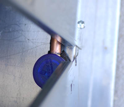
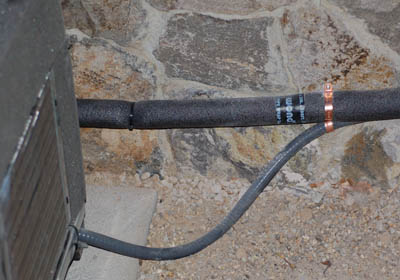
Horizontal siteglass is nice, better readings than vertical orientation. But this is too close to the edge. The hood flange hits the siteglass when the case is closed (the hood must be opened to access the valves so the flange on the other side hits the liquid line.)
Why is there cork tape around the cutout? It does not protect a sharp edge, the metal goes right through it. It also glues the hood closed. It also sticks to the insulation on the lineset and peels off and makes a mess. It also makes us look like a garage band when other contractors on a site look at our stuff. It is just that obviously off base. If it is desirable to trim the hole (and it isn't) use press on edging. It is available in small sizes at low cost on big spools. A piece is included with some hoods to trim the cutout around the condensing coil.
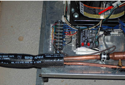
Note the pipe insulation projecting into the case. This is what the cork tape is going to adhere to instead of the sheet metal.. It is also what makes the cork tape unnecessary. The wiring is run under the lineset for protection.
Note the red arrow pointing to the 'button' stuck to the side of the compressor. The compressor gets hot. Immediately. The button falls off and dangles from the wire. Immediately. This is not theory, it is a simple observation. I do not think the person who built this has ever observed one of these machines in operation.
There are further issues. The entire liquid line was insulated from the base with a carefully applied layer of cork tape. The line was also cleverly run through a slit in the front foam to keep it warm. Unfortunately the entire object is to cool this line as much as possible. This is why we bind our linesets in a common jacket. It makes the entire lineset into a heat exchanger; the liquid line is cooled and the suction line is heated. And we don't have to buy a separate heat exchanger to do it. Insulating the liquid line at the condenser (where it is hottest) get everything off to exactly the wrong start. Again, whomever is building these does not understand how they work or what we want to achieve. They did do a nice job of it however and scraping off all the cork tape just so I could cut and braze the suction line took awhile. They have never installed one of these either. They seem conscientious and if they had broader experience with installing and servicing I imagine they would come up with strong solutions.
Just my opinion of course.
Several machines now have come in with these weatherproof junction boxes lashed on to them. Several problems here:
- The box serves no purpose. The hood itself is a junction box as long as there are naked high voltage terminals in it. The service wiring should run directly into the hood from below.
- The box is no longer weather tight because there is a hole in the back of it with BX cable running through it. Anything but the most vertically falling rain will soak this connection...never mind a sprinkler head.
- BX cable is for inside use only. It can be used on the interior of a machine or the interior of a building. It cannot be exposed to the weather, cannot be floating 2" off the ground (outside), cannot be terminated within 2" of the exposed edge of a machine (even though it is underneath), etc.
- The box is mounted so that it covers one of the mounting holes in the base flange. These holes are used to bolt the machine down. Some contractors require us to bolt the machine to a slab. Sometimes I bolt them if I suspect the customer may try to move them. Other times I am mounting in a Unistrut frame and the holes are used to bolt to the strut.
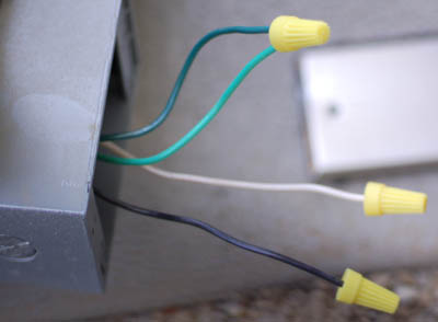
Note also that this machine is 240VAC. This means that in the picture above both the white and black legs are "hot". White wire can never be used as a power leg; the wire must be black, red or blue. If white is used it must be re-labeled with colored tape. Consult the NEC section 170 for the relabeling spec. (I just wrap it with a lot of red tape)
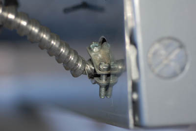
This is the hole in the backside of the box. Note the broken BX housing. Several machines have come in with the BX broken this way. The sharp edges of the metal cut into the wire (Terminating BX cable is where you do use the red bushings!). This is poor craftsmanship and a very real hazard. As a rule a cable clamp should always be installed so that the clamping screws are accessible with the assembly completed. DO NOT install a clamp by holding the nut and turning the clamp (with the cable in it). This is what is damaging the BX. Hold the clamp, face it in the right direction and turn the nut. Proper pliers are important. I use Facom 180.TE pliers. They are French made and very, very good. They are also superb for opening the plastic strain reliefs on the evaporators. No more struggles with those. I found them at OSH.
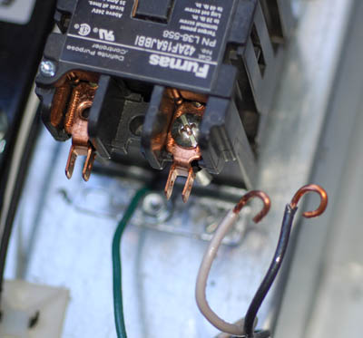
Very nice loops. Spade connections are used on the other side of the contactor so why are loops used here? They are slow to make and slower to get apart. Wrong color wire and it is going somewhere it doesn't need to go to do something that not only doesn't need doing but has to be undone for safety and function reasons.
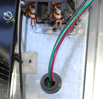
Liquitite fitting from the inside. These wires run directly to the disconnect panel. No other junction boxes are required. It is a 240VAC installation so red and black for the power and green for the ground. If we wanted to split off 110VAC inside the machine we would go with four wires and the fourth would be the white neutral. Look inside the panel of a chillertech machine and you will see this. The compressors are 240 and the transformers are 110.
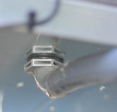
Liquitite fitting from underneath the machine. A right angle fitting is used. On the other end of the Liquitite cable a strait fitting goes into the bottom of the disconnect box.
Note the drip loop. It is pretty small here and the cable lies on the ground (not desirable) but the customer wanted the machine low and the pad set into the ground. Shouldn't hurt anything. The important thing is that the cable runs uphill into all fittings. This is a code issue. Water does not run uphill.
A book on elementary wiring (available at Home Depot, go for the glossy one with pictures) will illustrate all of this stuff. There is no reason to make any of it up or try to invent things. It is standard stuff. It is covered in books and it may be observed on any of the other equipment found on a jobsite.
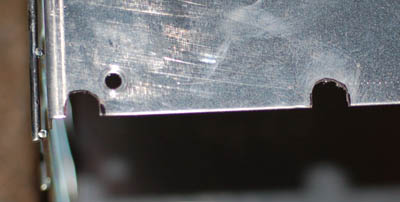
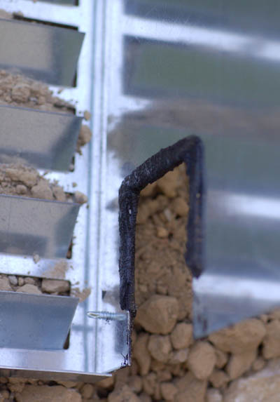
This bullshit needs to stop. I discovered this little experiment at 11:30 at night while scrambling to get the machine sewn up. I noticed when opening up the hood that the factory screws had not been used but I was distracted trying to pry apart the spot glued together with cork tape (TAKE THE TAPE AWAY FROM THAT GUY!!!) and didn't noticed the attempt at making slots. They are in the wrong place, are badly made (they are bigger than the damn screws!), they involved drilling a separate set of holes in the mating surface and they are only on the backside (which in this installation is 6" off a stone wall). So I go to put it together and I zip my screws in the holes and it turns out I hit the holes from the slot experiment and the whole thing goes together awry...and it takes a while to figure out why the frame is warped and the entire machine is rocking on the vibration mounts. I got it eventually and I was extremely pissed off (and still am. It was a hard night 150 miles from home and I just didn't need it)
I have a lot of years of machine design experience on my resume. Slotting those holes is a seemingly obvious move. Adding a ledger screw is also obvious. The Manufacturer uses slots and ledges in other locations...so why not here? I decided months ago not to do any slotting until I had that one thought through. And if I do any I'll do it right for crissakes...think Milwaukee angle head shear. It makes a slot just the size of that screw body. Even a pair of snips will work. But you do need to understand what a slot is and how it works. For production work they should be punched.
Note 2-7-2007: I now slot all my base screw holes and tape the two halves of the hood together (water intrusion issues). I use a pair of Wiss M5 snips to slot the holes. Takes less than 1 min. to do them all. I sent a pair of these snips up to Chuck to give to production.

Evaporator assembled on site. The thing came in the original packaging, undamaged and with all the needed bits included in the box. Assembling on site was a snap and the lines run just where I need them to, they are simply laid out, there is the required access to the Superheat adjustment and the orifice screen. No time wasted reworking. (100% or the ones I have received to date have been wrong).
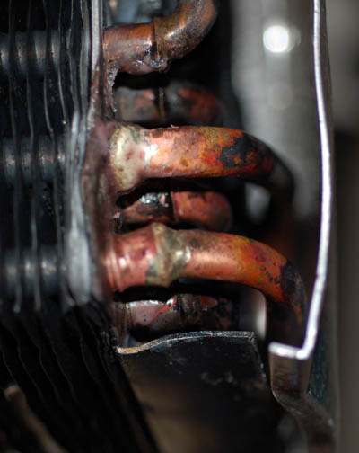
For Chuck, you wanted to see this repair:
When bad things happen to good evaporators. It fell from the ceiling (this is a chillertech replacement and I am working over fully stocked racking. My support board kicked out on the canvas I had things draped with ), took a bounce off the steel scaffold and hit the tile on one corner. Looked bad but the frame straitened out fairly well and the dinged panels are hidden behind the wood screen. The completely crushed connecting tube was the real problem. Getting the crushed tube out was tough. Next time, saw it out then pull the orifice and blow the thing out. The fins draw so much heat that melting the factory braze is very difficult. Replacement tube is bent to a pair of 90's descending to a 180 a few inches down. Gave enough flex to line it all up. I used both the jaw expander and a hammer mandrel to open up the evap. tubes enough to fit. Tube was annealed before the final braze. Brazing was with a pair of MAP torches using 45% silver 1/8" wire and white flux. Not pretty but it holds 250 PSI with microleak solution. My OxyActylene Microtorch is too much to carry and work like this is (hopefully) extremely rare. Seems to work OK. It is on the last turn of the output side of the top (of 2) coil so it mostly gas at this point.