 |
This is a simple circuit I designed to dump/program the ATMEL AT29C256 flash using a standard bi-directional parallel port. The ATMEL flash devices can be ordered from Pioneer Standard for around $5 each.
Schematic capture and layout were accomplished using EAGLE Light from CadSoft. Considering that it is free (as in beer), it is a decent tool. If you see areas for improvement in this design, please don't hesitate to let me know!
|
| Signal | Description |
|---|---|
| #AHEN (U1:9) | Address HIGH Register Enable (select) |
| #ALEN (U1:12) | Address LOW Register Enable (select) |
| #FLEN (U1:11) | Flash Enable (select) |
| DATA[0:7] | 8-bit Data Bus |
| ADDR[0:14] | 15-bit Flash Address |
| /LINEFEED | Device Address (select) low bit |
| /INITIALIZE | Device Address (select) high bit |
| /SELECT | Read/Write (Low = Read) |
| /STROBE | Load Data (on low going pulse) |
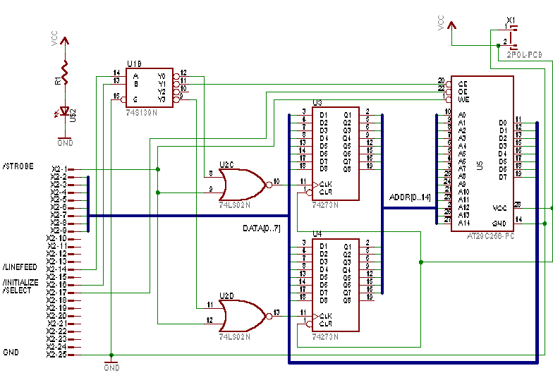
The 15-bit flash address is written into the two 8-bit registers, one byte at a time. 8-bits of data is then written to (or read from) the flash device. The "initialize" and "auto-linefeed" signals are used as a 2-bit "device address" to select which device will be written to (address high register, address low register, or flash device). Note that the flash data is read/write, whereas the address registers are write-only.
To perform a write operation to a device, first the device address is set, then the data is presented on DATA[0:7] and a low-going pulse is sent on the STROBE line. Note: Remember that some signals in the parallel port control/status registers are inverted by the hardware!!!
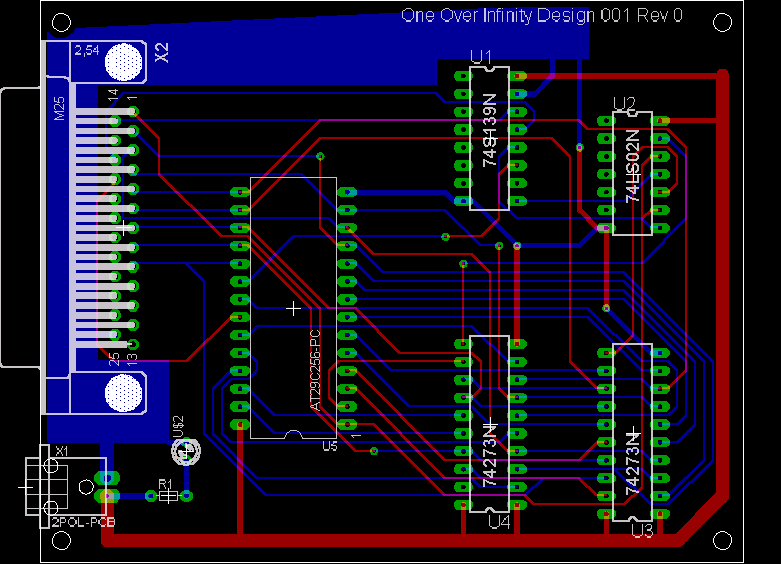
Currently, the programmer is prototyped on a couple of breadboards from Radio Shack. I'm looking into having a PCB fabricated.
 |
| Ref. | Qty. | Part # | Description |
|---|---|---|---|
| X2 | 1 | N/A | Standard DB25 Male Connector |
| U1 | 1 | 74HCT139 | 2-line to 4-line Decoder |
| U2 | 1 | 74HCT02N | Quadruple 2-input Positive NOR Gates |
| U3,U4 | 2 | 74HCT273 | Octal D-Type Flip-Flop with Clear |
| U$2 | 1 | N/A | LED for indicating "power on" (optional) |
| R1 | 1 | N/A | 1k-ohm 1/4-watt resistor for "power on" LED (optional) |
| N/A | 1 | N/A | 28-pin ZIF socket for flash (optional) |
| N/A | 2 | 276-174 | Archer Experimenter Socket (Radio Shack standard breadboard) (optional) |
| N/A | 1 | 273-1695 | Radio Shack Digital Camera Power Supply (3-6.5V, 2.5A) |
| N/A | 1 | N/A | Radio Shack 2-wire breadboard adapter for power supply |
I need to clean up the source code before I post it. Contact me if you would like me to send you a copy via e-mail.