100. The Art And Science Of Navigation
 Marine navigation blends both science and art. A good navigator constantly thinks strategically, operationally, and tactically. He plans each voyage carefully. As it proceeds, he gathers navigational information from a variety of sources, evaluates this information, and determines his ship’s position. He then compares that position with his voyage plan, his operational commitments, and his predetermined “dead reckoning” position. A good navigator anticipates dangerous situations well before they arise, and always stays “ahead of the vessel.” He is ready for navigational emergencies at any time. He is increasingly a manager of a variety of resources–electronic, mechanical, and human. Navigation methods and techniques vary with the type of vessel, the conditions, and the navigator’s experience. The navigator uses the methods and techniques best suited to the vessel, its equipment, and conditions at hand. Some important elements of successful navigation cannot be acquired from any book or instructor. The science of navigation can be taught, but the art of navigation must be developed from experience.
101. Types of Navigation
 Methods of navigation have changed throughout history. New methods often enhance the mariner’s ability to complete his voyage safely and expeditiously, and make his job easier. One of the most important judgments the navigator must make involves choosing the best methods to use. Each method or type has advantages and disadvantages, while none is effective in all situations. Commonly recognized types of navigation are listed below.
- Dead reckoning (DR) determines position by advancing a known position for courses and distances. A position so determined is called a dead reckoning (DR) position. It is generally accepted that
- only course and speed determine the DR position. Correcting the DR position for leeway, current effects, and steering error result in an estimated position (EP).
- Piloting involves navigating in restricted waters with frequent or constant determination of position relative to nearby geographic and hydrographic features.
- Celestial navigation involves reducing celestial measurements taken with a sextant to lines of position using calculators or computer programs, or by hand with almanacs and tables or using spherical trigonometry.
- Radio navigation uses radio waves to determine position through a variety of electronic devices.
- Radar navigation uses radar to determine the distance from or bearing of objects whose position is known. This process is separate from radar’s use in collision avoidance.
- Satellite navigation uses radio signals from satellites for determining position.

Rafting at Spencer Spit with “Ahelani,” my sister’s Outbound 48.
Electronic systems and integrated bridge concepts are driving navigation system planning. Integrated systems take inputs from various ship sensors, electronically and automatically chart the position, and provide control signals required to maintain a vessel on a preset course. The navigator becomes a system manager, choosing system presets, interpreting system output, and monitoring vessel response. In practice, a navigator synthesizes different methodologies into a single integrated system. He should never feel comfortable utilizing only one method when others are also available. Each method has advantages and disadvantages. The navigator must choose methods appropriate to each situation, and never rely completely on only one system. With the advent of automated position fixing and electronic charts, modern navigation is almost completely an electronic process. The mariner is constantly tempted to rely solely on electronic systems. But electronic navigation systems are always subject to failure, and the professional mariner must never forget that the safety of his ship and crew may depend on skills that differ little from those practiced generations ago.  Proficiency in conventional piloting and celestial navigation remains essential.
102. Phases of Navigation
 Four distinct phases define the navigation process. The mariner should choose the system mix that meets the accuracy requirements of each phase.
- Inland Waterway Phase: Piloting in narrow canals, channels, rivers, and estuaries.
- Harbor/Harbor Approach Phase: Navigating to a harbor entrance through bays and sounds, and negotiating harbor approach channels.
- Coastal Phase: Navigating within 50 miles of the coast or inshore of the 200 meter depth contour.
- Ocean Phase: Navigating outside the coastal area in the open sea.
The navigator’s position accuracy requirements, his fix interval, and his systems requirements differ in each phase. The following table can be used as a general guide for selecting the proper system(s). Inland Harbor/ Approach Coastal Ocean DR X X X X Piloting X X X Celestial X X Radio X X X Radar X X X Satellite X* X X X
103. Important Conventions and Concepts
 Throughout the history of navigation, numerous terms and conventions have been established which enjoy worldwide recognition. The professional navigator, to gain a full understanding of his field, should understand the origin of certain terms, techniques, and conventions. The following section discusses some of the important ones. Defining a prime meridian is a comparatively recent development. Until the beginning of the 19th century, there was little uniformity among cartographers as to the meridian from which to measure longitude. But it mattered little because there existed no method for determining longitude accurately. Ptolemy, in the 2nd century AD, measured longitude eastward from a reference meridian 2 degrees west of the Canary Islands.
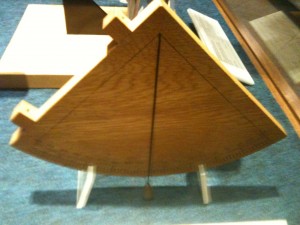
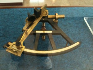
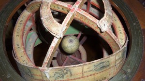
Quadrant (15th Century) Instrument used for measuring the altitude of the stars in order to calculate the latitude. First made in wood, like this replica, they were later made of brass or bronze.
In 1493, Pope Alexander VI established a line in the Atlantic west of the Azores to divide the territories of Spain and Portugal. For many years, cartographers of these two countries used this dividing line as the prime meridian. In 1570 the Dutch cartographer Ortelius used the easternmost of the Cape Verde Islands. John Davis, in his 1594 The Seaman’s Secrets, used the Isle of Fez in the Canaries because there the variation was zero. Most mariners paid little attention to these conventions and often reckoned their longitude from several different capes and ports during a voyage. The meridian of London was used as early as 1676, and over the years its popularity grew as England’s maritime interests increased. The system of measuring longitude both east and west through 180° may have first appeared in the middle of the 18th century. Toward the end of that century, as the Greenwich Observatory increased in prominence, English cartographers began using the meridian of that observatory as a reference. The publication by the Observatory of the first British Nautical Almanac in 1767 further entrenched Greenwich as the prime meridian. An unsuccessful attempt was made in 1810 to establish Washington, D.C. as the prime meridian for American navigators and cartographers. In 1884, the meridian of Greenwich was officially established as the prime meridian. Today, all maritime nations have designated the Greenwich meridian the prime meridian, except in a few cases where local references are used for certain harbor charts.
Charts are graphic representations of areas of the Earth, in digital or graphic form, for use in marine or air navigation. Nautical charts, whether in digital or paper form, depict features of particular interest to the marine navigator. Charts have probably existed since at least 600 B.C. Stereographic and orthographic projections date from the 2nd century B.C.  In 1569 Gerardus Mercator published a chart using the mathematical principle which now bears his name. Some 30 years later, Edward Wright published corrected mathematical tables for this projection, enabling other cartographers to produce charts on the Mercator projection. This projection is still the most widely used. Sailing Directions or pilots have existed since at least the 6th century B.C. Continuous accumulation of navigational data, along with increased exploration and trade, led to increased production of volumes through the Middle Ages.
  “Routiers” were produced in France about 1500; the English referred to them as “rutters.” In 1584 Lucas Waghenaer published the Spieghel der Zeevaerdt (The Mariner’s Mirror), which became the model for such publications for several generations of navigators. They were known as “Waggoners” by most sailors. The compass was developed about 1000 years ago.</p>
Table 102. The relationship of the types and phases of navigation. * With SA off and/or using DGPS The origin of the magnetic compass is uncertain, but Norsemen used it in the 11th century, and Chinese navigators used the magnetic compass at least that early and probably much earlier. It was not until the 1870s that Lord Kelvin developed a reliable dry card marine compass. The fluid-filled compass became standard in 1906. Variation was not understood until the 18th century, when Edmond Halley led an expedition to map lines of variation in the South Atlantic. Deviation was understood at least as early as the early 1600s, but adequate correction of compass error was not possible until Matthew Flinders discovered that a vertical iron bar could reduce certain types of errors. After 1840, British Astronomer Royal Sir George Airy and later Lord Kelvin developed combinations of iron masses and small magnets to eliminate most magnetic compass error. The gyrocompass was made necessary by iron and steel ships. Leon Foucault developed the basic gyroscope in 1852. An American (Elmer Sperry) and a German (Anshutz Kampfe) both developed electrical gyrocompasses in the early years of the 20th century. Ring laser gyrocompasses and digital flux gate compasses are gradually replacing traditional gyrocompasses, while the magnetic compass remains an important backup device.  The log is the mariner’s speedometer. Mariners originally measured speed by observing a chip of wood passing down the side of the vessel. Later developments included a wooden board attached to a reel of line. Mariners measured speed by noting how many knots in the line unreeled as the ship moved a measured amount of time; hence the term knot. Mechanical logs using either a small paddle wheel or a rotating spinner arrived about the middle of the 17th century. The taffrail log still in limited use today was developed in 1878. Modern logs use electronic sensors or spinning devices that induce small electric fields proportional to a vessel’s speed. An engine revolution counter or shaft log often measures speed aboard large ships. Doppler speed logs are used on some vessels for very accurate speed readings. Inertial and satellite systems also provide highly accurate speed readings. The Metric Conversion Act of 1975 and the Omnibus Trade and Competitiveness Act of 1988 established the metric system of weights and measures in the United States. As a result, the government is converting charts to the metric format. Notwithstanding the conversion to the metric system, the common measure of distance at sea is the nautical mile. The current policy of the National Imagery and Mapping Agency (NIMA) and the National Ocean Service (NOS) is to convert new compilations of nautical, special purpose charts, and publications to the metric system. All digital charts use the metric system. This conversion began on January 2, 1970. Most modern maritime nations have also adopted the meter as the standard measure of depths and heights. However, older charts still on issue and the charts of some foreign countries may not conform to this standard. The fathom as a unit of length or depth is of obscure origin. Posidonius reported a sounding of more than 1,000 fathoms in the 2nd century B.C. How old the unit was then is unknown. Many modern charts are still based on the fathom, as conversion to the metric system continues. The sailings refer to various methods of mathematically determining course, distance, and position. They have a history almost as old as mathematics itself. Thales, Hipparchus, Napier, Wright, and others contributed the formulas that permit computation of course and distance by plane, traverse, parallel, middle latitude, Mercator, and great circle sailings.
104. The Earth
 The Earth is an irregular oblate spheroid (a sphere flattened at the poles). Measurements of its dimensions and the amount of its flattening are subjects of geodesy. However, for most navigational purposes, assuming a spherical Earth introduces insignificant error. The Earth’s axis of rotation is the line connecting the north and south geographic poles. A great circle is the line of intersection of a sphere and a plane through its center. This is the largest circle that can be drawn on a sphere. The shortest line on the surface of a sphere between two points on the surface is part of a great circle. On the spheroidal Earth the shortest line is called a geodesic. A great circle is a near enough approximation to Figure 104a. The planes of the meridians at the polar axis. a geodesic for most problems of navigation. A small circle is the line of intersection of a sphere and a plane which does not pass through the center. See Figure 104a. The term meridian is usually applied to the upper branch of the half-circle from pole to pole which passes through a given point. The opposite half is called the lower branch. A parallel or parallel of latitude is a circle on the surface of the Earth parallel to the plane of the equator. It connects all points of equal latitude. The equator is a great circle at latitude 0°. See Figure 104b. The poles are single points at latitude 90°. All other parallels are small circles.
105. Coordinates

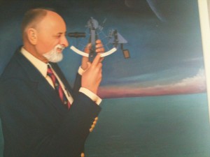
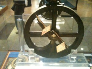
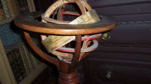
The Reflecting Circle (18th Century) was also called the Gunwale Circle. It was used to find the longitude by measuring the horizontal angle between the moon and the stars of the zodiac.
Coordinates of latitude and longitude can define any position on Earth. Latitude (L, lat.) is the angular distance from the equator, measured northward or southward along a meridian from 0° at the equator to 90° at the poles. It is designated north (N) or south (S) to indicate the direction of measurement.The difference of latitude (l, DLat.) between two places is the angular length of arc of any meridian between their parallels. It is the numerical difference of the latitudes if the places are on the same side of the equator; it is the sum of the latitudes if the places are on opposite sides of the equator. It may be designated north (N) or south (S) when appropriate. The middle or mid-latitude (Lm) between two places on the same side of the equator is half the sum of their latitudes. Mid-latitude is labeled N or S to indicate whether it is north or south of the equator. The expression may refer to the mid-latitude of two places on opposite sides of the equator. In this case, it is equal to half the difference between the two latitudes and takes the name of the place farthest from the equator. Longitude (l, long.) is the angular distance between the prime meridian and the meridian of a point on the Earth, measured eastward or westward from the prime meridian through 180°. It is designated east (E) or west (W) to indicate the direction of measurement. The difference of longitude (DLo) between two places is the shorter arc of the parallel or the smaller angle at the pole between the meridians of the two places. If both places are on the same side (east or west) of Greenwich, DLo is the numerical difference of the longitudes of the two places; if on opposite sides, DLo is the numerical sum unless this exceeds 180°, when it is 360° minus the sum. The distance between two meridians at any parallel of latitude, expressed in distance units, usually nautical miles, is called departure (p, Dep.). It represents distance made good east or west as a craft proceeds from one point to another. Its numerical value between any two meridians decreases with increased latitude, while DLo is numerically the same at any latitude. Either DLo or p may be designated east (E) or west (W) when appropriate.
106. Distance on the Earth
al angle between the moon and the stars of the zodiac.
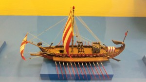
Spain and Portugal division of World
Distance, as used by the navigator, is the length of the rhumb line connecting two places. This is a line making the same angle with all meridians. Meridians and parallels which also maintain constant true directions may be considered special cases of the rhumb line. Any other rhumb line spirals toward the pole, forming a loxodromic curve or loxodrome. See Figure 106. Figure 104b. The equator is a great circle midway between the poles. Figure 106. A loxodrome. Distance along the great circle connecting two points is customarily designated great-circle distance. For most purposes, considering the nautical mile the length of one minute of latitude introduces no significant error. Speed (S) is rate of motion, or distance per unit of time.A knot (kn.), the unit of speed commonly used in navigation, is a rate of 1 nautical mile per hour. The expression speed of advance (SOA) is used to indicate the speed to be made along the intended track. Speed over the ground (SOG) is the actual speed of the vessel over the surface of the Earth at any given time. To calculate speed made good (SMG) between two positions, divide the distance between the two positions by the time elapsed between the two positions.
107. Direction on the Earth
Direction is the position of one point relative to another. Navigators express direction as the angular difference in degrees from a reference direction, usually north or the ship’s head. Course (C, Cn) is the horizontal direction in which a vessel is intended to be steered, expressed as angular distance from north clockwise through 360°. Strictly used, the term applies to direction through the water, not the direction intended to be made good over the ground.The course is often designated as true, magnetic, compass, or grid according to the reference direction. Track made good (TMG) is the single resultant direction from the point of departure to point of arrival at any given time. Course of advance (COA) is the direction intended to be made good over the ground, and course over ground (COG) is the direction between a vessel’s last fix and an EP. A course line is a line drawn on a chart extending in the direction of a course. It is sometimes convenient to express a course as an angle from either north or south, through 90° or 180°. In this case it is designated course angle (C) and should be properly labeled to indicate the origin (prefix) and direction of measurement (suffix). Thus, C N35°E = Cn 035° (000° + 35°), C N155°W = Cn 205° (360° – 155°), C S47°E = Cn 133° (180° – 47°). But Cn 260° may be either C N100°W or C S80°W, depending upon the conditions of the problem. Track (TR) is the intended horizontal direction of travel with respect to the Earth. The terms intended track and trackline are used to indicate the path of intended travel. See Figure 107a. The track consists of one or a series of course lines, from the point of departure to the destination, along which one intends to proceed. A great circle which a vessel intends to follow is called a great-circle track, though it consists of a series of straight lines approximating a great circle Heading (Hdg., SH) is the direction in which a vessel is pointed at any given moment, expressed as angular distance from 000° clockwise through 360°. It is easy to confuse heading and course. Heading constantly changes as a vessel yaws back and forth across the course due to sea, wind, and steering error. Bearing (B, Brg.) is the direction of one terrestrial point from another, expressed as angular distance from 000° (North) clockwise through 360°. When measured through 90° or 180° from either north or south, it is called bearing angle (B). Bearing and azimuth are sometimes used interchangeably, but the latter more accurately refers to the horizontal direction of a point on the celestial sphere from a point on the Earth. A relative bearing is measured relative to the ship’s heading from 000° (dead ahead) clockwise through 360°. However, it is sometimes conveniently measured right or left from 000° at the ship’s head through 180°. This is particularly true when using the table for Distance of an Object by Two Bearings. Figure 107a. Course line, track, track made good, and heading. To convert a relative bearing to a true bearing, add the true heading. See Figure 107b True Bearing = Relative Bearing + True Heading. Relative Bearing = True Bearing – True Heading.
108. Finding Latitude and Longitude
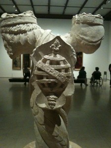
THe Ericeira Astrolabe
Navigators have made latitude observations for thousands of years. Accurate declination tables for the Sun have been published for centuries, enabling ancient seamen to compute latitude to within 1 or 2 degrees. Those who today determine their latitude by measuring the Sun at their meridian and the altitude of Polaris are using methods well known to 15th century navigators. A method of finding longitude eluded mariners for centuries. Several solutions independent of time proved too cumbersome. Finding longitude by magnetic variation was tried, but found too inaccurate. The lunar distance method, which determines GMT by observing the Moon’s position among the stars, became popular in the 1800s. However, the mathematics required by most of these processes were far above the abilities of the average seaman. It was apparent that the solution lay in keeping accurate time at sea.
lunar eclipses, lunar distances, the satellites of Jupiter, and other solutions to the longitude problem had been proposed besides the marine chronometer.
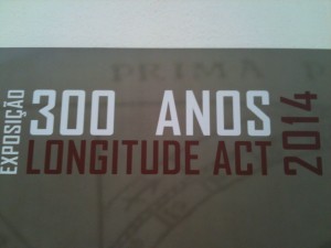
In 1714, the British Board of Longitude was formed, offering a small fortune in reward to anyone who could provide a solution to the problem. An Englishman, John Harrison, responded to the challenge, developing four chronometers between 1735 and 1760. The most accurate of these timepieces lost only 15 seconds on a 156 day round trip between London and Barbados. The Board, however, paid him only half the promised reward. The King finally intervened on Harrison’s behalf, and at the age of 80 years Harrison received his full reward of £20,000. Rapid chronometer development led to the problem of determining chronometer error aboard ship. Time balls, large black spheres mounted in port in prominent locations, were dropped at the stroke of noon, enabling any ship in harbor which could see the ball to determine chronometer error. By the end of the U.S. Civil War, telegraph signals were being used to key time balls. Use of radio signals to send time ticks to ships well offshore began in 1904, and soon worldwide signals were available.
109. The Navigational Triangle
Modern celestial navigators reduce their celestial observations by solving a navigational triangle whose points are the elevated pole, the celestial body, and the zenith of the observer. The sides of this triangle are the polar distance of the body (codeclination), its zenith distance (coaltitude), and the polar distance of the zenith (colatitude of the observer). A spherical triangle was first used at sea in solving lunar distance problems. Simultaneous observations were made of the altitudes of the Moon and the Sun or a star near the ecliptic and the angular distance between the Moon and the other body. The zenith of the observer and the two celestial bodies formed the vertices of a triangle whose sides were the two coaltitudes and the angular distance between the bodies. Using a mathematical calculation the navigator “cleared” this distance of the effects of refraction and parallax applicable to each altitude. This corrected value was then used as an argument for entering the almanac. The almanac gave the true lunar distance from the Sun and several stars at 3 hour intervals. Previously, the Figure 107b. Relative Bearing navigator had set his watch or checked its error and rate with the local mean time determined by celestial observations. The local mean time of the watch, properly corrected, applied to the Greenwich mean time obtained from the lunar distance observation, gave the longitude. The calculations involved were tedious. Few mariners could solve the triangle until Nathaniel Bowditch published his simplified method in 1802 in The New American Practical Navigator. Reliable chronometers were available by1800, but their high cost precluded their general use aboard most ships. However, most navigators could determine their longitude using Bowditch’s method. This eliminated the need for parallel sailing and the lost time associated with it. Tables for the lunar distance solution were carried in the American nautical almanac into the 20th century.
110. The Time Sight
 The theory of the time sight had been known to mathematicians since the development of spherical trigonometry, but not until the chronometer was developed could it be used by mariners. The time sight used the modern navigational triangle. The codeclination, or polar distance, of the body could be determined from the almanac. The zenith distance (coaltitude) was determined by observation. If the colatitude were known, three sides of the triangle were available. From these the meridian angle was computed. The comparison of this with the Greenwich hour angle from the almanac yielded the longitude.
The time sight was mathematically sound, but the navigator was not always aware that the longitude determined was only as accurate as the latitude, and together they merely formed a point on what is known today as a line of position. If the observed body was on the prime vertical, the line of position ran north and south and a small error in latitude generally had little effect on the longitude. But when the body was close to the meridian, a small error in latitude produced a large error in longitude. Figure 110. The first celestial line of position, obtained by Captain Thomas Sumner in1837. The line of position by celestial observation was unknown until discovered in 1837 by 30-year-old Captain Thomas H. Sumner, a Harvard graduate and son of a United States congressman from Massachusetts. The discovery of the “Sumner line,” as it is sometimes called, was considered by Maury “the commencement of a new era in practical navigation.” This was the turning point in the development of modern celestial navigation technique. In Sumner’s own words, the discovery took place in this manner:
Having sailed from Charleston, S. C., 25th November, 1837, bound to Greenock, a series of heavy gales from the Westward promised a quick passage; after passing the Azores, the wind prevailed from the Southward, with thick weather; after passing Longitude 21° W, no observation was had until near the land; but soundings were had not far, as was supposed, from the edge of the Bank. The weather was now more boisterous, and very thick; and the wind still Southerly; arriving about midnight, 17th December, within 40 miles, by dead reckoning, of Tusker light; the wind hauled SE, true, making the Irish coast a lee shore; the ship was then kept close to the wind, and several tacks made to preserve her position as nearly as possible until daylight; when nothing being in sight, she was kept on ENE under short sail, with heavy gales; at about 10 AM an altitude of the Sun was observed, and the Chronometer time noted; but, having run so far without any observation, it was plain the Latitude by dead reckoning was liable to error, and could not be entirely relied on. Using, however, this Latitude, in finding the Longitude by Chronometer, it was found to put the ship 15′ of Longitude E from her position by dead reckoning; which in Latitude 52°Nis 9 nautical miles; this seemed to agree tolerably well with the dead reckoning; but feeling doubtful of the Latitude, the observation was tried with a Latitude 10′ further N, finding this placed the ship ENE 27 nautical miles, of the former position, it was tried again with a Latitude 20′ N of the dead reckoning; this also placed the ship still further ENE, and still 27 nautical miles further; these three positions were then seen to lie in the direction of Small’s light. It then at once appeared that the observed altitude must have happened at all the three points, and at Small’s light, and at the ship, at the same instant of time; and it followed, that Small’s light must bear ENE, if the Chronometer was right. Having been convinced of this truth, the ship was kept on her course, ENE, the wind being still SE., and in less than an hour, Small’s light was made bearing ENE 1/2 E, and close aboard.
In 1843 Sumner published a book, A New and Accurate Method of Finding a Ship’s Position at Sea by Projection on Mercator’s Chart. He proposed solving a single time sight twice, using latitudes somewhat greater and somewhat less than that arrived at by dead reckoning, and joining the two positions obtained to form the line of position. The Sumner method required the solution of two time sights to obtain each line of position. Many older navigators preferred not to draw the lines on their charts, but to fix their position mathematically by a method which Sumner had also devised and included in his book. This was a tedious but popular procedure.
111. Navigational Tables
 Spherical trigonometry is the basis for solving every navigational triangle, and until about 80 years ago the navigator had no choice but to solve each triangle by tedious, manual computations. Lord Kelvin, generally considered the father of modern navigational methods, expressed interest in a book of tables with which a navigator could avoid tedious trigonometric solutions. However, solving the many thousands of triangles involved would have made the project too costly. Computers finally provided a practical means of preparing tables. In 1936 the first volume of Pub. No. 214 was made available; later, Pub. No. 249 was provided for air navigators. Pub. No. 229, Sight Reduction Tables for Marine Navigation, has replaced Pub. No. 214. Electronic calculators are gradually replacing the tables. Scientific calculators with trigonometric functions can easily solve the navigational triangle. Navigational calculators readily solve celestial sights and perform a variety of voyage planning functions. Using a calculator generally gives more accurate lines of position because it eliminates the rounding errors inherent in tabular inspection and interpolation.
112. Development of Electronic Navigation
 Perhaps the first application of electronics to navigation involved sending telegraphic time signals in 1865 to check chronometer error. Transmitting radio time signals for chronometer checks dates to 1904. Radio broadcasts providing navigational warnings, begun in 1907 by the U.S. Navy Hydrographic Office, helped increase the safety of navigation at sea. By the latter part of World War I the directional properties of a loop antenna were successfully used in the radio direction finder. The first radiobeacon was installed in 1921. Early 20th century experiments by Behm and Langevin led to the U.S. Navy’s development of the first practical echo sounder in 1922. Radar and hyperbolic systems grew out of WWII. Today, electronics touches almost every aspect of navigation. Hyperbolic systems, satellite systems, and electronic charts all require an increasingly sophisticated electronics suite and the expertise to manage them. These systems’ accuracy and ease of use make them invaluable assets to the navigator, but there is far more to using them than knowing which buttons to push.
113. Development of Radar
As early as 1904, German engineers were experimenting with reflected radio waves. In 1922 two American scientists, Dr. A. Hoyt Taylor and Leo C. Young, testing a communication system at the Naval Aircraft Radio Laboratory, noted fluctuations in the signals when ships passed between stations on opposite sides of the Potomac River. In 1935 the British began work on radar. In 1937 the USS Leary tested the first sea-going radar, and in 1940 United States and British scientists combined their efforts. When the British revealed the principle of the multicavity magnetron developed by J. T. Randall and H. A. H. Boot at the University of Birmingham in 1939, microwave radar became practical. In 1945, at the close of World War II, radar became available for commercial use.
114. Development of Hyperbolic Radio Aids
Various hyperbolic systems were developed beginning in World War II. These were outgrowths of the British GEE system, developed to help bombers navigate to and from their missions over Europe. Loran A was developed as a long-range marine navigation system. This was replaced by the more accurate Loran C system, deployed throughout much of the world. Various short range and regional hyperbolic systems have been developed by private industry for hydrographic surveying, offshore facilities positioning, and general navigation.
115. Other Electronic Systems
The underlying concept that led to development of satellite navigation dates to 1957 and the first launch of an artificial satellite into orbit. The first system, NAVSAT, has been replaced by the far more accurate and widely available Global Positioning System (GPS), which has revolutionized all aspects of navigation  The first inertial navigation system was developed in 1942 for use in the V2 missile by the Peenemunde group under the leadership of Dr. Wernher von Braun. This system used two 2-degree-of-freedom gyroscopes and an integrating accelerometer to determine the missile velocity. By the end of World War II, the Peenemunde group had developed a stable platform with three single-degree-of-freedom gyroscopes and an integrating accelerometer. In 1958 an inertial navigation system was used to navigate the USS Nautilus under the ice to the North Pole.
116. Governmental Role
US Navy Bells, following English tradition are still used (inverted) as baptismal founts. Names of the Baptized are inscribed inside the bell.
Navigation only a generation ago was an independent process, carried out by the mariner without outside assistance. With compass and charts, sextant and chronometer, he could independently travel anywhere in the world. The increasing use of electronic navigation systems has made the navigator dependent on many factors outside his control. Government organizations fund, operate, and regulate satellites, Loran, and other electronic systems. Governments are increasingly involved in regulation of vessel movements through traffic control systems and regulated areas. Understanding the governmental role in supporting and regulating navigation is vitally important to the mariner. In the United States, there are a number of official organizations which support the interests of navigators. Some have a policy-making role; others build and operate navigation systems. Many maritime nations have similar organizations performing similar functions. International organizations also play a significant role.
117. The Coast and Geodetic Survey
The U.S. Coast and Geodetic Survey was founded in 1807 when Congress passed a resolution authorizing a survey of the coast, harbors, outlying islands, and fishing banks of the United States. President Thomas Jefferson appointed Ferdinand Hassler, a Swiss immigrant and professor of mathematics at West Point, the first Director of the “Survey of the Coast.” The survey became the “Coast Survey” in 1836. The approaches to New York were the first sections of the coast charted, and from there the work spread northward and southward along the eastern seaboard. In 1844 the work was expanded and arrangements made to simultaneously chart the gulf and east coasts. Investigation of tidal conditions began, and in 1855 the first tables of tide predictions were published. The California gold rush necessitated a survey of the west coast, which began in 1850, the year California became a state. Coast Pilots, or Sailing Directions, for the Atlantic coast of the United States were privately published in the first half of the 19th century. In 1850 the Survey began accumulating data that led to federally produced Coast Pilots. The 1889 Pacific Coast Pilot was an outstanding contribution to the safety of west coast shipping.<p> In 1878 the survey was renamed “Coast and Geodetic Survey.” In 1970 the survey became the “National Ocean Survey,” and in 1983 it became the “National Ocean Service.” The Office of Charting and Geodetic Services accomplished all charting and geodetic functions. In 1991 the name was changed back to the original “Coast and Geodetic Survey,” organized under the National Ocean Service along with several other environmental offices. Today it provides the mariner with the charts and coast pilots of all waters of the United States and its possessions, and tide and tidal current tables for much of the world. Its administrative order requires the Coast and Geodetic Survey to plan and direct programs to produce charts and related information for safe navigation of U.S. waterways, territorial seas, and airspace. This work includes all activities related to the National Geodetic Reference System; surveying, charting, and data collection; production and distribution of charts; and research and development of new technologies to enhance these missions.
118. The National Imagery and Mapping Agency
In the first years of the newly formed United States of America, charts and instruments used by the Navy and merchant mariners were left over from colonial days or were obtained from European sources. In 1830 the U.S. Navy established a “Depot of Charts and Instruments” in Washington, D. C., as a storehouse from which available charts, pilots and sailing directions, and navigational instruments were issued to Naval ships. Lieutenant L. M. Goldsborough and one assistant, Passed Midshipman R. B. Hitchcock, constituted the entire staff. The first chart published by the Depot was produced from data obtained in a survey made by Lieutenant Charles Wilkes, who had succeeded Goldsborough in 1834. Wilkes later earned fame as the leader of a United States expedition to Antarctica. From 1842 until 1861 Lieutenant Matthew Fontaine Maury served as Officer in Charge. Under his command the Depot rose to international prominence. Maury decided upon an ambitious plan to increase the mariner’s knowledge of existing winds, weather, and currents. He began by making a detailed record of pertinent matter included in old log books stored at the Depot. He then inaugurated a hydrographic reporting program among ship masters, and the thousands of reports received, along with the log book data, were compiled into the “Wind and Current Chart of the North Atlantic” in 1847. This is the ancestor of today’s Pilot Chart. The United States instigated an international conference in 1853 to interest other nations in a system of exchanging nautical information. The plan, which was Maury’s, was enthusiastically adopted by other maritime nations. In 1854 the Depot was redesignated the “U.S. Naval Observatory and Hydrographical Office.” At the outbreak of the American Civil War in 1861, Maury, a native of Virginia, resigned from the U.S. Navy and accepted a commission in the Confederate Navy. This effectively ended his career as a navigator, author, and oceanographer. At war’s end, he fled the country, his reputation suffering from his embrace of the Confederate cause. After Maury’s return to the United States in 1868, he served as an instructor at the Virginia Military Institute. He continued at this position until his death in 1873. Since his death, his reputation as one of America’s greatest hydrographers has been restored. In 1866 Congress separated the Observatory and the Hydrographic Office, broadly increasing the functions of the latter. The Hydrographic Office was authorized to carry out surveys, collect information, and print every kind of nautical chart and publication “for the benefit and use of navigators generally.” The Hydrographic Office purchased the copyright of The New American Practical Navigator in 1867. The first Notice to Mariners appeared in 1869. Daily broadcast of navigational warnings was inaugurated in 1907. In 1912, following the sinking of the Titanic, the International Ice Patrol was established. In 1962 the U.S. Navy Hydrographic Office was redesignated the U.S. Naval Oceanographic Office. In 1972 certain hydrographic functions of the latter office were transferred to the Defense Mapping AgencyHydrographic Center. In 1978 the Defense Mapping Agency Hydrographic/Topographic Center (DMAHTC) assumed hydrographic and topographic chart production functions. In 1996 the National Imagery and Mapping Agency (NIMA) was formed from DMA and certain other elements of the Department of Defense.NIMA continues to produce charts and publications and to disseminate maritime safety information in support of the U.S. military and navigators generally. 119. The United States Coast Guard Alexander Hamilton established the U.S. Coast Guard as the Revenue Marine, later the Revenue Cutter Service, on August 4, 1790. It was charged with enforcing the customs laws of the new nation. A revenue cutter, the Harriet Lane, fired the first shot from a naval unit in the Civil War at Fort Sumter. The Revenue Cutter Service became the U.S. Coast Guard when combined with the Lifesaving Service in 1915. The Lighthouse Service was added in 1939, and the Bureau of Marine Inspection and Navigation was added in 1942. The Coast Guard was transferred from the Treasury Department to the Department of Transportation in 1967. The primary functions of the Coast Guard include maritime search and rescue, law enforcement, and operation of the nation’s aids to navigation system. In addition, the Coast Guard is responsible for port safety and security, merchant marine inspection, and marine pollution control. The Coast Guard operates a large and varied fleet of ships, boats, and aircraft in performing its widely ranging duties Navigation systems operated by the Coast Guard include the system of some 40,000 lighted and unlighted beacons, buoys, and ranges in U.S. and territorial waters; the U.S. stations of the Loran C system; differential GPS (DGPS) services in the U.S.; and Vessel Traffic Services (VTS) in major ports and harbors of the U.S.
120. The United States Navy
 The U.S. Navy was officially established in 1798. Its role in the development of navigational technology has been singular. From the founding of the Naval Observatory to the development of the most advanced electronics, the U.S. Navy has been a leader in developing devices and techniques designed to make the navigator’s job safer and easier. The development of almost every device known to navigation science has been deeply influenced by Naval policy. Some systems are direct outgrowths of specific Naval needs; some are the result of technological improvements shared with other services and with commercial maritime industry.
121. The United States Naval Observatory
 One of the first observatories in the United States was built in 1831-1832 at Chapel Hill, N.C. The Depot of Charts and Instruments, established in 1830, was the agency from which the U.S. Navy Hydrographic Office and the U.S. Naval Observatory evolved 36 years later. In about 1835, under Lieutenant Charles Wilkes, the second Officer in Charge, the Depot installed a small transit instrument for rating chronometers. The Mallory Act of 1842 provided for the establishment of a permanent observatory. The director was authorized to purchase everything necessary to continue astronomical study. The observatory was completed in 1844 and the results of its first observations were published two years later. Congress established the Naval Observatory as a separate agency in 1866. In 1873 a refracting telescope with a 26 inch aperture, then the world’s largest, was installed. The observatory, located in Washington, D.C., has occupied its present site since 1893.
122. The Royal Greenwich Observatory
 England had no early privately supported observatories such as those on the continent. The need for navigational advancement was ignored by Henry VIII and Elizabeth I, but in 1675 Charles II, at the urging of John Flamsteed, Jonas Moore, Le Sieur de Saint Pierre, and Christopher Wren, established the Greenwich Royal Observatory. Charles limited construction costs to £500, and appointed Flamsteed the first Astronomer Royal, at an annual salary of £100. The equipment available in the early years of the observatory consisted of two clocks, a “sextant” of 7 foot radius, a quadrant of 3 foot radius, two telescopes, and the star catalog published almost a century before by Tycho Brahe. Thirteen years passed before Flamsteed had an instrument with which he could determine his latitude accurately. In 1690 a transit instrument equipped with a telescope and vernier was invented by Romer; he later added a vertical circle to the device. This enabled the astronomer to determine declination and right ascension at the same time. One of these instruments was added to the equipment at Greenwich in 1721, replacing the huge quadrant previously used. The development and perfection of the chronometer in the next hundred years added to the accuracy of observations. Other national observatories were constructed in the years that followed: at Berlin in 1705, St. Petersburg in 1725, Palermo in 1790, Cape of Good Hope in 1820, Parramatta in New South Wales in 1822, and Sydney in 1855.
123. The International Hydrographic Organization
The International Hydrographic Organization (IHO) was originally established in 1921 as the International Hydrographic Bureau (IHB). The present name was adopted in 1970 as a result of a revised international agreement among member nations. However, the former name, International Hydrographic Bureau, was retained for the IHO’s administrative body of three Directors and their staff at the organization’s headquarters in Monaco. The IHO sets forth hydrographic standards to be agreed upon by the member nations. All member states are urged and encouraged to follow these standards in their surveys, nautical charts, and publications. As these standards are uniformly adopted, the products of the world’s hydrographic and oceanographic offices become more uniform. Much has been done in the field of standardization since the Bureau was founded. The principal work undertaken by the IHO is:
- To bring about a close and permanent association between national hydrographic offices.
- To study matters relating to hydrography and allied sciences and techniques.
- To further the exchange of nautical charts and documents between hydrographic offices of member governments.
- To circulate the appropriate documents.
- To tender guidance and advice upon request, in particular to countries engaged in setting up or expanding their hydrographic service.
- To encourage coordination of hydrographic surveys with relevant oceanographic activities.
- To extend and facilitate the application of oceanographic knowledge for the benefit of navigators.
- To cooperate with international organizations and scientific institutions which have related objectives.
 During the 19th century, many maritime nations established hydrographic offices to provide means for improving the navigation of naval and merchant vessels by providing nautical publications, nautical charts, and other navigational services. There were substantial differences in hydrographic procedures, charts, and publications. In 1889, an International Marine Conference was held at Washington, D. C., and it was proposed to establish a “permanent international commission.” Similar proposals were made at the sessions of the International Congress of Navigation held at St. Petersburg in 1908 and again in 1912. In 1919 the hydrographers of Great Britain and France cooperated in taking the necessary steps to convene an international conference of hydrographers. London was selected as the most suitable place for this conference, and on July 24, 1919, the First International Conference opened, attended by the hydrographers of 24 nations. The object of the conference was “To consider the advisability of all maritime nations adopting similar methods in the preparation, construction, and production of their charts and all hydrographic publications; of rendering the results in the most convenient form to enable them to be readily used; of instituting a prompt system of mutual exchange of hydrographic information between all countries; and of providing an opportunity to consultations and discussions to be carried out on hydrographic subjects generally by the hydrographic experts of the world.” This is still the major purpose of the International Hydrographic Organization. As a result of the conference, a permanent organization was formed and statutes for its operations were prepared.
  The International Hydrographic Bureau, now the International Hydrographic Organization, began its activities in 1921 with 18 nations as members. The Principality of Monaco was selected because of its easy communication with the rest of the world and also because of the generous offer of Prince Albert I of Monaco to provide suitable accommodations for the Bureau in the Principality. There are currently 59 member governments. Technical assistance with hydrographic matters is available through the IHO to member states requiring it. Many IHO publications are available to the general public, such as the International Hydrographic Review, International Hydrographic Bulletin, Chart Specifications of the IHO, Hydrographic Dictionary, and others. Inquiries should be made to the International Hydrographic Bureau, 7 Avenue President J. F. Kennedy, B.P. 445, MC98011, Monaco, CEDEX. 124. The International Maritime Organization The International Maritime Organization (IMO) was established by United Nations Convention in 1948. The Convention actually entered into force in 1959, although an international convention on marine pollution was adopted in 1954. (Until 1982 the official name of the organization was the Inter-Governmental Maritime Consultative Organization.) It is the only permanent body of the U. N. devoted to maritime matters, and the only special U. N. agency to have its headquarters in the UK. The governing body of the IMO is the Assembly of 137 member states, which meets every two years. Between Assembly sessions a Council, consisting of 32 member governments elected by the Assembly, governs the organization. Its work is carried out by the Maritime Safety Committee, with subcommittees for:
- Safety of Navigation
- Radiocommunications
- Life-saving
- Search and Rescue
- Training and Watchkeeping
- Carriage of Dangerous Goods
- Ship Design and Equipment
- Fire Protection
- Stability and Load Lines/Fishing Vessel Safety
- Containers and Cargoes
- Bulk Chemicals
- Marine Environment Protection Committee
- Legal Committee
- Technical Cooperation Committee
- Facilitation Committee
 IMO is headed by the Secretary General, appointed by the council and approved by the Assembly. He is assisted by some 300 civil servants. To achieve its objectives of coordinating international policy on marine matters, the IMO has adopted some 30 conventions and protocols, and adopted over 700 codes and recommendations. An issue to be adopted first is brought before a committee or subcommittee, which submits a draft to a conference. When the conference adopts the final text, it is submitted to member governments for ratification. Ratification by a specified number of countries is necessary for adoption; the more important the issue, the more countries must ratify. Adopted conventions are binding on member governments. Codes and recommendations are not binding, but in most cases are supported by domestic legislation by the governments involved. The first and most far-reaching convention adopted by the IMO was the Convention of Safety of Life at Sea (SOLAS) in 1960. This convention actually came into force in 1965, replacing a version first adopted in 1948. Because of the difficult process of bringing amendments into force internationally, none of subsequent amendments became binding. To remedy this situation, a new convention was adopted in 1974 and became binding in 1980. Among the regulations is V-20, requiring the carriage of up-to-date charts and publications sufficient for the intended voyage. Other conventions and amendments were also adopted, such as the International Convention on Load Lines (adopted 1966, came into force 1968), a convention on the tonnage measurement of ships (adopted 1969, came into force 1982), The International Convention on Safe Containers (adopted 1972, came into force 1977), and the convention on International Regulations for Preventing Collisions at Sea (COLREGS) (adopted 1972, came into force 1977). The 1972 COLREGS convention contained, among other provisions, a section devoted to Traffic Separation Schemes, which became binding on member states after having been adopted as recommendations in prior years. One of the most important conventions is the International Convention for the Prevention of Pollution from Ships (MARPOL 73/78), which was first adopted in 1973, amended by Protocol in 1978, and became binding in 1983. This convention built on a series of prior conventions and agreements dating from 1954, highlighted by several severe pollution disasters involving oil tankers.
  The MARPOL convention reduces the amount of oil discharged into the sea by ships, and bans discharges completely in certain areas. A related convention known as the London Dumping Convention regulates dumping of hazardous chemicals and other debris into the sea. The IMO also develops minimum performance standards for a wide range of equipment relevant to safety at sea. Among such standards is one for the Electronic Chart Display and Information System (ECDIS), the digital display deemed the operational and legal equivalent of the conventional paper chart. Texts of the various conventions and recommendations, as well as a catalog and publications on other subjects, are available from the Publications Section of the IMO at 4 Albert Embankment, London SE1 7SR, United Kingdom. 125. The International Association of Marine Aids to Navigation and Lighthouse Authorities The International Association of Marine Aids to Navigation and Lighthouse Authorities (formerly IALA) brings together representatives of the aids to navigation services of more than 80 member countries for technical coordination, information sharing, and coordination of improvements to visual aids to navigation throughout the world. It was established in 1957 to provide a permanent organization to support the goals of the Technical Lighthouse Conferences, which had been convening since 1929. The General Assembly of IALA meets about every 4 years. The Council of 20 members meets twice a year to oversee the ongoing programs. Five technical committees maintain the permanent programs:
- The Marine Marking Committee
- The Radionavigation Systems Committee
- The Vessel Traffic Services (VTS) Committee
- The Reliability Committee
- The Documentation Committee
 IALA committees provide important documentation to the IHO and other international organizations, while the IALA Secretariat acts as a clearing house for the exchange of technical information, and organizes seminars and technical support for developing countries. Its principle work since 1973 has been the implementation of the IALA Maritime Buoyage System, described in Chapter 5, Visual Aids to Navigation. This system replaced some 30 dissimilar buoyage systems in use throughout the world with 2 major systems. IALA is based near Paris, France in Saint-Germaineen- Laye. 126. The Radio Technical Commission for Maritime Services The Radio Technical Commission for Maritime Services is a non-profit organization which serves as a focal point for the exchange of information and the development of recommendations and standards related to all aspects of maritime radiocommunications and radionavigation. Specifically, RTCM: • Promotes ideas and exchanges information on maritime radiocommunications and radionavigation. • Facilitates the development and exchange of views among and between government and nongovernment interests both nationally and internationally. • Conducts studies and prepares reports on maritime radiocommunications and radionavigation issues to improve efficiency and capabilities. Both government and non-government organizations are members, coming from the U.S. and many other nations.
  The RTCM organization consists of a Board of Directors, and the Assembly consisting of all members, officers, staff, technical advisors, and working committees. Working committees are formed as needed to develop official RTCM recommendations regarding technical standards and regulatory policies in the maritime field. Currently committees address such issues as maritime safety information, electronic charts, emergency position-indicating radiobeacons (EPIRB’s), personal locator beacons, ship radars, differential GPS, GLONASS, and maritime survivor locator devices. The RTCM headquarters office is in Alexandria, VA. 127. The National Marine Electronic Association The National Marine Electronic Association (NMEA) is a professional trade association founded in 1957 whose purpose is to coordinate the efforts of marine electronics manufacturers, technicians, government agencies, ship and boat builders, and other interested groups. In addition to certifying marine electronics technicians and professionally recognizing outstanding achievements by corporate and individual members, the NMEA sets standards for the exchange of digital data by all manufacturers of marine electronic equipment. This allows the configuration of integrated navigation system using equipment from different manufacturers. NMEA works closely with RTCM and other private organizations and with government agencies to monitor the status of laws and regulations affecting the marine electronics industry. It also sponsors conferences and seminars, and publishes a number of guides and periodicals for members and the general public.
128. International Electrotechnical Commission
 The International Electrotechnical Commission (IEC) was founded in 1906 as an outgrowth of the International Electrical Congress held at St. Louis, Missouri in 1904. Some 60 countries are active members. Its mission is to develop and promote standardization among all nations in the technical specifications of electrical and electronic equipment. These technologies include electronics, magnetics, electromagnetics, electroacoustics, multimedia, telecommunications, electrical energy production and distribution, and associated fields such as terminology and symbology, compatibility, performance standards, safety, and environmental factors.
  By standardizing in these areas, the IEC seeks to promote more efficient markets, improve the quality of products and standards of performance, promote interoperability, increase production efficiency, and contribute to human health and safety and environmental protection. Standards are published by the IEC in the form of official IEC documents after debate and input from the national committees.
Standards thus represent a consensus of the views of many different interests. Adoption of a standard by any country is entirely voluntary. However, failure to adopt a standard may result in a technical barrier to trade, as goods manufactured to a proprietary standard in one country may be incompatible with the systems of others. IEC standards are vital to the success of ECDIS and other integrated navigation systems because they help to ensure that systems from various manufacturers in different countries will be compatible and meet required specifications.


One thought on “MARINE NAVIGATION”